STEP BY STEP PROCESS Installation of the Flow Meter and Telemetry

(STEP 1) FOR INSTALLING A FLOW METER

Step 1 for Connecting Communication Cable

Step 1 => Open the back side cap of the Flow Meter & Connect the communication cable on TX+ and Tx-

  • TX+ => Red
  • TX- => Black

If the Power cable is not Connected then on the L point connect the Phase and on the N point connect the Neutral Cable.

Note: There is an Earthing point on the back side of the Flow Meter that should be connected for the safety of the Flow Meter.


(STEP 2) FOR INSTALLING THE SIM IN THE TELEMETRY SYSTEM

SIM INSTALLATION IN TELEMETRY

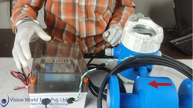
Step 2 => Open the Lid of the Telemetry Box by removing the 4 screws. 

Remove the antenna for easy removal of the Telemetry System from the Box and Push the Telemetry downwards. 

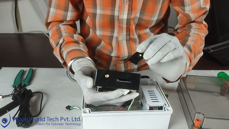
Use a small Sim Removal pin for Extracting the SIM Slot. 

SIM slot will be the size of a MINI SIM.

(STEP 3) CONNECTING FLOW METER WITH TELEMETRY SYSTEM

Connecting Flow Meter and telemetry

Step 3 => After the Successful installation of the SIM, We have to Reconnect the Antenna and Close the Upper lid.

Now Connect the Communication cable of the Flow Meter and the Telemetry System 

Communication Cable Color Code 

  • Green TX+
  • White TX-


10/10

WATCH FULL VIDEO FOR STEP BY STEP PROCESS

The above process for Installation of The Flow Meter and Telemetry is based on the Products designed by Vision World Tech Pvt Ltd. We provide solutions for CGWA-based Ground Water Monitoring Applications, Flow Monitoring Applications & Remote Monitoring Applications. 

For any kind of 

Technical Query: +91-7742715000

Sales Query: +91-8505000822

Mail Us: admin@visionworldtech.com